Cheap Home Assistant – ESP32 Velux Window control
Automating a Velux wireless remote — solid-state, one chip.
Wire an ESP32-C3 Super Mini across the three buttons of a Velux io-homecontrol remote so it can press ▲ STOP ▼ over Wi-Fi. No relays: a single quad optocoupler IC does all three buttons with full electrical isolation between the ESP32 and the remote’s coin-cell circuit.
Relays vs. solid state
A Velux remote runs from a 3 V coin cell (or 2×AAA). When you press a button you’re closing a contact that carries a few microamps at ~3 V into a microcontroller input. That is the easiest switching job in electronics — a mechanical relay is enormous overkill: it’s bulky, clicks audibly, draws 30–70 mA of coil current from your ESP32’s 3.3 V rail, and still needs a driver transistor and flyback diode per channel.
LTV-847 / TLP281-4
Quad optocoupler, DIP-16 (or SOIC). LED in, phototransistor out. Full galvanic isolation, no shared ground needed, ~$0.50. Only quirk: the output is polarized, so you check pad polarity with a multimeter once.
AQY212 / TLP222A PhotoMOS
Solid-state relay in a DIP-4/6 IC package. MOSFET output conducts either direction, so no polarity check needed. Behaves exactly like a relay contact. ~$2–3 each, and you need three.
CD4066 analog switch
Quad bilateral switch, one IC. But it needs a shared ground between ESP32 and remote and the switched voltage must stay inside its supply rails — you lose isolation and gain failure modes. Skip it here.
Mechanical relay ×3
Three relays + three transistors + three diodes + three resistors, audible clicking, high coil current. Only worth it if you already own a relay board and hate soldering DIPs.
Bill of materials
| Ref | Part | Value / type | Purpose |
|---|---|---|---|
| U1 | ESP32-C3 Super Mini | — | Wi-Fi brain; drives the opto LEDs from GPIO |
| U2 | LTV-847 (or TLP281-4) | Quad optocoupler, DIP-16 | Solid-state “fingers” across the 3 buttons |
| R1–R3 | Resistor | 220 Ω, 1/4 W (260 Ω works fine) | Sets opto LED current to ~8–9 mA per channel |
| R4–R6 | Resistor | 10 kΩ, 1/4 W | Pull-downs: pin each GPIO to 0 V during boot/reset/flash so the opto LEDs can never glimmer and ghost-press a button |
| — | Thin hookup wire | 30 AWG wire-wrap or enameled | Soldering to the remote’s button pads |
| — | DIP-16 socket (optional) | — | Lets you swap the opto without desoldering |
| — | USB-C supply | 5 V | Powers the ESP32; remote keeps its own battery |
The two ends of the link
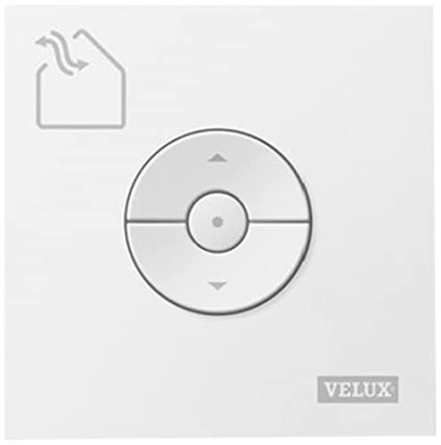

Find and test the button pads
Open the remote (usually 2–4 small Torx/Phillips screws under the battery cover). Each of the three buttons — ▲ up, ■ stop, ▼ down — is a dome-type tact switch or membrane pad with two electrical sides. You need two things per button: a solderable point on each side, and its polarity.
- Locate the pads. Follow the traces from each button. Tact switches usually have 4 legs in two internally-joined pairs — confirm pairs with a continuity beep. Look for nearby test points or vias; they’re easier to solder than switch legs.
- Find the polarity. Battery in, remote on. Set your multimeter to DC volts, black probe on battery negative. Probe both sides of a button: one side reads ~3 V (the pulled-up MCU input — this is the + side) and the other reads ~0 V (ground side). Note which is which for all three buttons.
- Dry-run the press. Briefly short the two sides with tweezers. The window should respond exactly as if you pressed the button. If it does, the optocoupler will work.
- Solder six wires. One wire to each side of each button (6 total). Use thin wire, minimal heat, and a dab of hot glue or Kapton over the joints for strain relief. Route the wires out through the battery compartment or a small notch filed in the case.
Circuit diagram
Three identical channels. Left side: each GPIO is held at 0 V by a 10 kΩ pull-down (so boot, reset, and flashing can never ghost-press a button) and drives its opto LED through 220 Ω — anode at top, cathode to ground. Right side: each phototransistor sits across one button — collector to the button’s + pad, emitter to its ground-side pad. The two halves share nothing but light.
Pin-to-pin wiring table
LTV-847 pinout: LED anodes on pins 1, 3, 5, 7; cathodes on 2, 4, 6, 8; transistor collectors on 16, 14, 12, 10; emitters on 15, 13, 11, 9. Channel 1 = pins 1/2 in, 16 (C) / 15 (E) out, and so on. Channel 4 is left unused.
| Button | ESP32-C3 pin | Via | Opto LED (A / K) | Opto output (C / E) | Remote pads |
|---|---|---|---|---|---|
| ▲ Up | GPIO5 | R1 220Ω | 1 / 2 → GND | 16 (C) / 15 (E) | C→button + pad, E→button GND-side pad |
| ■ Stop | GPIO6 | R2 220Ω | 3 / 4 → GND | 14 (C) / 13 (E) | C→button + pad, E→button GND-side pad |
| ▼ Down | GPIO7 | R3 220Ω | 5 / 6 → GND | 12 (C) / 11 (E) | C→button + pad, E→button GND-side pad |
GPIO2, GPIO8, GPIO9, whose state at power-up decides boot mode). Physically: on the Super Mini they’re three adjacent pins on the right-hand header, so on the protoboard all three drive signals exit one side of the module, directly facing the optocoupler — each 220 Ω resistor becomes a short straight bridge with no crossing wires. See the board layout below.Protoboard layout
Your board is the “solderable breadboard” style: each small oval pad joins 2–3 holes into one node, and long bus rails run the length of the board. That pattern decides the layout for you — components whose leads must connect share a pad group; everything else gets its own group. The whole build fits in a strip about 20 holes wide.
Placement rules for this board style
- Beep the pad groups first. Before soldering anything, use continuity mode to learn which holes each oval pad joins (yours mixes 2- and 3-hole groups) and which rails run the full length. Two minutes here prevents every phantom short later.
- ESP32 on the left, USB-C facing the board edge. The Super Mini spans 0.6″ — 6 holes between rows — so each pin row lands on its own pad group with free holes beside it for jumpers. Keep the antenna end (opposite USB) overhanging or clear of long parallel wires.
- Socket the LTV-847 one pad group to the right, notch up. Pin 1 at top-left puts the whole LED side (pins 1–8) facing the ESP32 and the whole output side (pins 9–16) facing the wire exit. Signal flows left→right; no wire ever crosses the IC.
- Resistors bridge the gap. R1–R3 span from the GPIO 5/6/7 pad groups to opto pins 1, 3, 5 — component leads double as the jumpers. Trim and re-use the clipped leads for the short GND links.
- Add the 10 kΩ pull-downs (R4–R6). One from each GPIO 5/6/7 pad group straight up to the GND bus rail, on the ESP32 side of the 220 Ω resistors. During reset, boot and firmware flashing the C3 floats its pins; the pull-downs hold them at 0 V so an opto LED can never glimmer and ghost-press a button. In normal use each costs a trivial 0.33 mA when its GPIO drives high. (Not drawn in FIG.2 — they sit vertically between the GPIO pads and the rail.)
- One GND node. Tie the ESP32
Gpin and opto cathodes 2, 4, 6 to the same bus rail. That rail is the only shared conductor on the input side — the output side touches nothing else on the board. - Give the 6 remote wires mechanical relief. Solder them at the exit pads, then loop each through an adjacent free hole before it leaves the board. Thin wire-wrap wire tears pads off when yanked; the loop takes the strain instead of the joint.
G pin.Firmware
A minimal Arduino sketch: connects to Wi-Fi, serves three endpoints, and “presses” a button by driving its GPIO high for 300 ms. In the Arduino IDE pick board ESP32C3 Dev Module and enable USB CDC On Boot so serial prints work over the USB-C port.
// Velux remote actuator — ESP32-C3 Super Mini + LTV-847
#include <WiFi.h>
#include <WebServer.h>

const char* ssid = "YOUR_WIFI";
const char* pass = "YOUR_PASSWORD";

const int PIN_UP   = 5;
const int PIN_STOP = 6;
const int PIN_DOWN = 7;
const int PRESS_MS = 300;   // hold long enough for the remote to register

WebServer server(80);

void press(int pin) {
  digitalWrite(pin, HIGH);   // LED on → phototransistor closes the "button"
  delay(PRESS_MS);
  digitalWrite(pin, LOW);
}

void setup() {
  Serial.begin(115200);
  for (int p : {PIN_UP, PIN_STOP, PIN_DOWN}) {
    pinMode(p, OUTPUT);
    digitalWrite(p, LOW);    // idle = button released
  }

  WiFi.mode(WIFI_STA);
  WiFi.begin(ssid, pass);
  while (WiFi.status() != WL_CONNECTED) delay(250);
  Serial.println(WiFi.localIP());

  server.on("/up",   []{ press(PIN_UP);   server.send(200, "text/plain", "up");   });
  server.on("/stop", []{ press(PIN_STOP); server.send(200, "text/plain", "stop"); });
  server.on("/down", []{ press(PIN_DOWN); server.send(200, "text/plain", "down"); });
  server.begin();
}

void loop() { server.handleClient(); }
Test from any device on your network: http://<esp-ip>/up, /stop, /down.
Prefer Home Assistant? Use ESPHome (position-aware)
This config dead-reckons the window’s position as seconds of travel from closed, held in RAM. Every preset — Vent (6.5 s), Half (27 s), Full (40 s), Closed — is a move-to-target: the script compares the target against the current estimate, picks ▲ or ▼ itself, runs for the difference, then presses ■ STOP. So Full → Vent closes for 33.5 s instead of forcing you back through fully-closed. Moves to the end stops (Full / Closed) deliberately overrun by 3 s and skip the STOP press, letting the window’s own limit switches re-zero the estimate — free re-calibration at both ends.
esphome:
  name: esp32-velux
  friendly_name: ESP32 velux
  platformio_options:
    board_build.flash_mode: dio
esp32:
  board: esp32-c3-devkitm-1
  variant: esp32c3
  flash_size: 4MB
  framework:
    type: esp-idf

logger:
# Enable Web server
web_server:
  port: 80

api:
  encryption:
    key: "abc123456789"
ota:
  - platform: esphome
    password: !secret ota_password

wifi:
  ssid: !secret wifi_ssid
  password: !secret wifi_password
  domain: .lan
  ap:
    ssid: ESP32 velux Fallback Hotspot
    password: "6CKmK3GuORn9"
captive_portal:

# ---- Position estimate, RAM only (seconds from closed) ---------
globals:
  - id: pos_s
    type: float
    restore_value: no        # memory only; unknown after reboot
    initial_value: '0.0'
  - id: moving_dir           # 1 = opening, -1 = closing, 0 = idle
    type: int
    restore_value: no
    initial_value: '0'
  - id: move_start_ms
    type: uint32_t
    restore_value: no
    initial_value: '0'

# ---- Raw button pressers (momentary, 300 ms) -------------------
switch:
  - platform: gpio
    pin: 5
    name: "Velux Up"
    id: velux_up
    on_turn_on:
      - delay: 300ms
      - switch.turn_off: velux_up
  - platform: gpio
    pin: 6
    name: "Velux Stop"
    id: velux_stop
    on_turn_on:
      - delay: 300ms
      - switch.turn_off: velux_stop
  - platform: gpio
    pin: 7
    name: "Velux Down"
    id: velux_down
    on_turn_on:
      - delay: 300ms
      - switch.turn_off: velux_down

# ---- Adjustable travel times (sliders in HA) -------------------
number:
  - platform: template
    name: "Time Vent Open"
    id: t_vent
    unit_of_measurement: "s"
    min_value: 0.5
    max_value: 15
    step: 0.5
    initial_value: 6.5
    restore_value: true
    optimistic: true
    mode: slider
  - platform: template
    name: "Time Half Open"
    id: t_half
    unit_of_measurement: "s"
    min_value: 1
    max_value: 60
    step: 0.5
    initial_value: 27
    restore_value: true
    optimistic: true
    mode: slider
  - platform: template
    name: "Time Full Open"
    id: t_full
    unit_of_measurement: "s"
    min_value: 5
    max_value: 90
    step: 0.5
    initial_value: 40
    restore_value: true
    optimistic: true
    mode: slider

# ---- Estimated position, visible in HA -------------------------
sensor:
  - platform: template
    name: "Window Position Estimate"
    unit_of_measurement: "%"
    accuracy_decimals: 0
    update_interval: 2s
    lambda: |-
      float p = id(pos_s);
      if (id(moving_dir) != 0) {
        p += id(moving_dir) * (millis() - id(move_start_ms)) / 1000.0f;
      }
      p = std::max(0.0f, std::min(p, id(t_full).state));
      return p / id(t_full).state * 100.0f;

# ---- Move to target: picks direction, runs the difference ------
script:
  - id: move_to
    mode: restart            # new command interrupts the old one cleanly
    parameters:
      target: float
    then:
      # reconcile the estimate if a previous move was cut short
      - lambda: |-
          if (id(moving_dir) != 0) {
            float elapsed = (millis() - id(move_start_ms)) / 1000.0f;
            id(pos_s) += id(moving_dir) * elapsed;
            id(pos_s) = std::max(0.0f, std::min(id(pos_s), id(t_full).state));
            id(moving_dir) = 0;
          }
      - if:
          condition:
            lambda: 'return target > id(pos_s) + 0.3f;'
          then:                # need to OPEN
            - lambda: |-
                id(moving_dir) = 1;
                id(move_start_ms) = millis();
            - switch.turn_on: velux_up
            - delay: !lambda |-
                float run = target - id(pos_s);
                if (target >= id(t_full).state) run += 3.0f;  // overrun to top stop
                return (uint32_t)(run * 1000);
            - if:
                condition:
                  lambda: 'return target < id(t_full).state;'
                then:
                  - switch.turn_on: velux_stop
            - lambda: |-
                id(pos_s) = std::min(target, id(t_full).state);
                id(moving_dir) = 0;
          else:
            - if:
                condition:
                  lambda: 'return target < id(pos_s) - 0.3f;'
                then:          # need to CLOSE
                  - lambda: |-
                      id(moving_dir) = -1;
                      id(move_start_ms) = millis();
                  - switch.turn_on: velux_down
                  - delay: !lambda |-
                      float run = id(pos_s) - target;
                      if (target <= 0.0f) run += 3.0f;  // overrun to bottom stop
                      return (uint32_t)(run * 1000);
                  - if:
                      condition:
                        lambda: 'return target > 0.0f;'
                      then:
                        - switch.turn_on: velux_stop
                  - lambda: |-
                      id(pos_s) = std::max(target, 0.0f);
                      id(moving_dir) = 0;

# ---- One-tap presets: move to position from wherever we are ----
button:
  - platform: template
    name: "Open to Vent"
    icon: "mdi:weather-windy"
    on_press:
      - script.execute:
          id: move_to
          target: !lambda 'return id(t_vent).state;'
  - platform: template
    name: "Open Half"
    icon: "mdi:window-open-variant"
    on_press:
      - script.execute:
          id: move_to
          target: !lambda 'return id(t_half).state;'
  - platform: template
    name: "Open Full"
    icon: "mdi:window-open"
    on_press:
      - script.execute:
          id: move_to
          target: !lambda 'return id(t_full).state;'
  - platform: template
    name: "Close Fully"
    icon: "mdi:window-closed"
    on_press:
      - script.execute:
          id: move_to
          target: !lambda 'return 0.0f;'
How the position tracking behaves
- After a reboot the estimate resets to 0 (closed) — it lives in RAM only. If the window wasn’t closed when the ESP32 restarted, tap Close Fully or Open Full once: the 3 s overrun into the end stop re-syncs the estimate regardless of where the window really was.
- Interrupted moves stay accurate. The script records when motion started; if you fire a new preset mid-travel, it first credits the elapsed time to the estimate, then computes the fresh move from there (
mode: restartmakes the handover clean). - End-stop moves self-calibrate. Open Full and Close Fully run 3 s past the expected travel and send no STOP — the window’s own limit stops it, and the estimate snaps to exactly full/zero. Any accumulated drift is wiped every time you fully open or close.
- The raw Up/Stop/Down switches bypass the tracker. Manual presses (on the remote or via the raw entities) desync the estimate — after using them, hit an end-stop preset to re-sync. Day-to-day, drive the window through the four preset buttons.
- The assumption baked in: opening and closing speeds are equal, which holds well for Velux chain actuators. If yours differs, the end-stop self-calibration absorbs the error anyway.
Calibrating the travel times
- Measure full travel first. From fully closed, hold ▲ on the real remote with a stopwatch until the motor stops at the top. Set Time Full Open to that (default 40 s). This number also scales the position sensor, so get it right before the others.
- Dial in Vent. Tap Close Fully, then Open to Vent and adjust the slider (default 6.5 s) until it stops right at the vent detent.
- Dial in Half. Roughly Time Full Open ÷ 2 — default 27 s suits a ~54 s window; adjust by eye. Slider changes apply instantly, no reflash.
!secret entries (ota_password, wifi_ssid, wifi_password) in your ESPHome secrets.yaml; consider regenerating the API key and AP password rather than shipping the ones in this listing.Bring-up checklist
- Bench-test the optos first. Before touching the remote: flash the sketch, put a multimeter in continuity mode across pins 15–16, hit
/up. You should hear a beep for ~300 ms. Repeat for the other channels. - Connect one button. Wire only the ▲ channel to the remote, trigger it, and watch the window. Working? Wire the other two.
- Confirm no ghost presses. Power-cycle the ESP32 a few times with the remote connected. GPIO 5/6/7 stay low through reset, so the remote should never react to a reboot.
If it doesn’t work
| Symptom | Likely cause | Fix |
|---|---|---|
| Continuity beep OK, remote ignores the press | C/E swapped on that channel | Swap the two wires at the remote pads — collector must go to the ~3 V pad |
| No beep across output pins | LED side miswired or resistor missing | Check anode→GPIO-via-R, cathode→GND; confirm ~1.2 V across LED pins when active |
| Remote reacts erratically / partial presses | Press too short | Raise PRESS_MS to 500 ms |
| Remote’s own physical buttons stopped working | Solder bridge across a switch | Inspect and reflow your joints; the opto in parallel never blocks manual use when idle |
| Remote locks up when connected; C–E off-resistance reads <1 MΩ | Leakage — flux residue on the board, or a leaky/counterfeit opto. Healthy dark C–E ≈ open (>10 MΩ); remotes use MΩ-class pull-ups, so 500 kΩ reads as half-pressed | Measure chip out of socket to split chip vs board; scrub board with IPA and dry; try spare channel 4 (pins 7/8 → 10/9) or a new chip; ultimate fix is AQY212 PhotoMOS (pA leakage) |
| Nothing works and pads read strangely | Matrix-scanned or unusual remote | Substitute AQY212 PhotoMOS per channel — polarity- and matrix-agnostic |